Printed Circuit Boards
Voltage Regulator
The first project in my electromechanical systems & robotics class was to create a breadboard power supply. The design comprised a PCB that plugged directly into a breadboard, accepted power from a 2.1 x 5.5 mm plug from a 12 V wall adapter, and emitted 12 V, 5 V, and 3.3 V.
I first assembled the circuit on a breadboard and tested it to ensure everything worked as expected before printing a PCB. Next, I drew a schematic on KiCad to illustrate the functions of the circuit, assigned footprints to components in the schematic to describe their physical structure, and designed the structure of the PCB itself. Once everything worked, I ordered the PCB board!

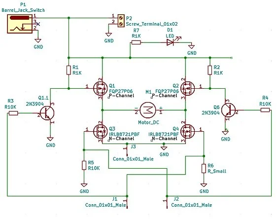


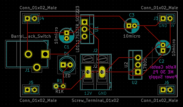
H-Bridge Motor Controller
The second project in my electromechanical systems & robotics class involved creating an H-bridge motor controller circuit and PCB board using KiCad. It was required to handle 12 V and 5 A continuously without melting, accept power from a 2.1 x 5.5 mm plug from a 12 V wall adapter, and be controllable by logic signals from an Arduino. Additionally, it featured a power LED that lit up when motor power was available.
Similar to the voltage regulator project, I initially assembled the circuit on a breadboard to ensure everything functioned correctly. Following this, I created a schematic on KiCad to illustrate the circuit's functions, assigned footprints to the components to describe their pin layout, and designed the structure of the PCB itself. Upon confirming everything worked as intended, I proceeded to order the PCB board!